ICE House Flight Path 30L at LANSCE
ICE House
The ICE House is an experimental area that is primarily used for semiconductor neutron irradiation research and testing. Many industry, laboratory, and university researchers have used this facility to qualify and test semiconductor device for single-event effects. It is located on a flight path at 30o to the left of the Target 4 neutron production target. The neutron spectrum for this area is shown in the Figure 1 and is very similar to the terrestrial neutron spectrum produced by cosmic rays hitting the atmosphere and ranges from approximately 1 MeV up to approximately 600 MeV. Because the ICE House neutron spectrum is similar to the terrestrial neutron spectrum, one can predict the failure rate of a device in a particular environment (neutron flux) by just scaling the flux intensities. The integrated neutron flux for the ICE House area above 1 (10) MeV is 2.4 x 10⁶ (1.2 x 10⁶) neutrons/cm2/sec.
Details of the testing facility and testing procedures are in the Los Alamos High-Energy Neutron Testing handbook.
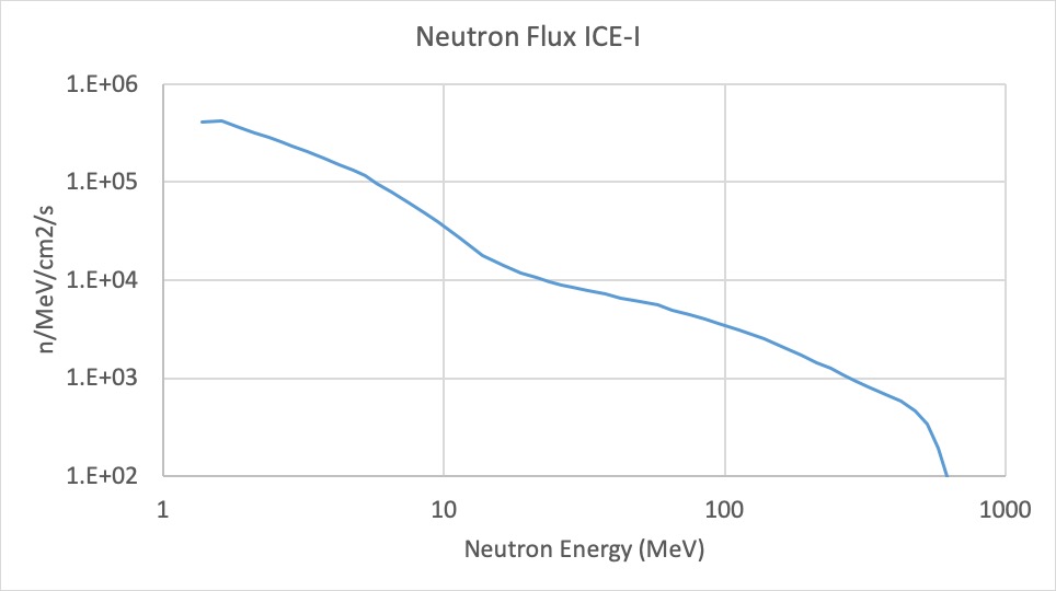
Figure 1.The neutron flux in units of neutrons/MeV/cm2/sec in the ICE House experimental area.
Figure 2 shows a schematic layout of the ICE House experimental area. The room is 40’ long by 20’ wide (800 sq ft). It is divided along the length into two sections. The upper area of the figure is the “beam area” and the lower part of the figure is the “work area”. The beam area is where the neutron beam enters from the right and exits the building on the left. The shielding wall which separates the two area consists of 22” thick concrete and polyethylene shielding. The beam area is approximately 13.5’ along the beam axis and approximately 9’ perpendicular to the beam axis. The shielding walls are 8 feet high. The center of the neutron beam is 37 inches above the floor and adequate AC power is available.
It is not possible to be in the beam area while the beam is on. Experimenters usually place their devices on lift tables near where the beam enters the building and connect their devices to their control computers in the work area. Cables between the devices and the control computer are approximately 20’ long and are passed over the shielding wall. An Ethernet cable and multiport switch is provided to connect the control computers to computers in a remote data room.
The neutron beam is controlled by a “shutter” which can be opened and closed by the experimenters. The neutron spot size is determined by collimation placed upstream of the experimental area. The present spot sizes are 1’, 2”, 3”, 4” and 4.5” in diameter.
The number of neutrons/cm2 passing through the devices is measured by a fission ionization chamber operated in time-of-flight mode. The experimenters are given TTL pulses that are proportional in number to the neutron fluence through the experimental setup. The experimenter can either count the number of pulses as part of their data stream or can use our counters and record the number at the end of their irradiation. The calibration constant that converts these pulses to neutrons/cm2 is measured continuously and given to the experimenters at least once/day or when conditions change.
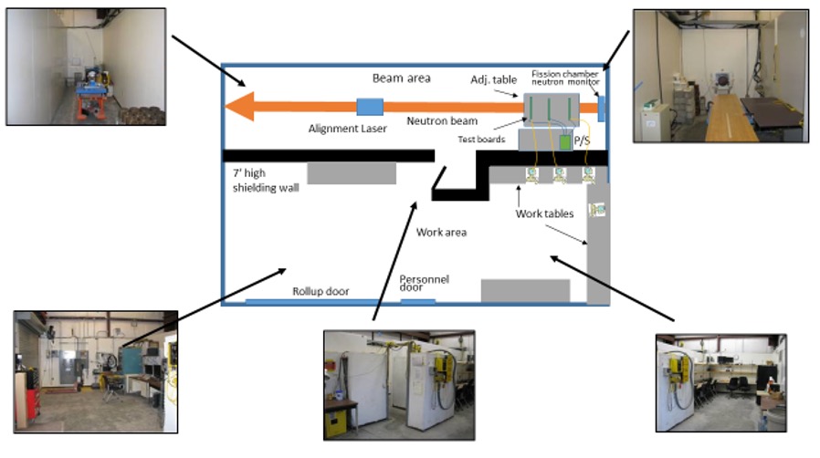
Figure 2. Layout of the ICE House experimental area.
Parameter for ICE House and ICE-II are given in the table below.
Parameters of the ICE House and ICE-II Experimental Areas
| ICE House | ICE II | |
| Height of beam above floor | 95 cm | 124.5 cm |
| Distance from production target to fission chamber | 19.67 m | 13.87 m |
| Integrated neutron intensity above 1.25 MeV | 2.4 106 n/cm2/sec | 4.7 106 n/cm2/sec |
| Integrated neutron intensity above 10 MeV | 1.2 106 n/cm2/sec | 2.2 106 n/cm2/sec |
| Beam spots available | 1”, 2”, 3”, 4”, 4.5” diam | 1”, 2”, 2.5”,3” diam |